[catlist name=ghostbox orderby=”date” order=”asc” excerpt=”no”]
You’ll Need the Following Supplies
-
- Arduino and USB cable
- Serial FM radio module with Amplifier
- male to female single pin jumper wires
More About your Supplies
 1 – Arduino and USB cable
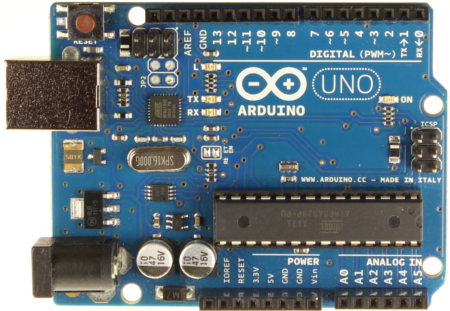
For this Project we will be using the Arduino Uno R3.
This is a processor board with built in interface for USB. Easily available from numerous sources including our own Ghost Box Hacks.
The Arduino Uno is a microcontroller board based on the ATmega328 (datasheet). It has 14 digital input/output pins (of which 6 can be used as PWM outputs), 6 analog inputs, a 16 MHz ceramic resonator, a USB connection, a power jack, an ICSP header and a reset button. It contains everything needed to support the microcontroller; simply connect it to a computer with a USB cable or power it with a AC-to-DC adapter or battery to get started.
There are several types of Arduino boards, however we will only be using the UNO. Most all the Adruino versions will work for these projects, but it may be easier for beginners to follow the Arduino Uno R3.
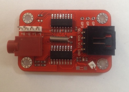
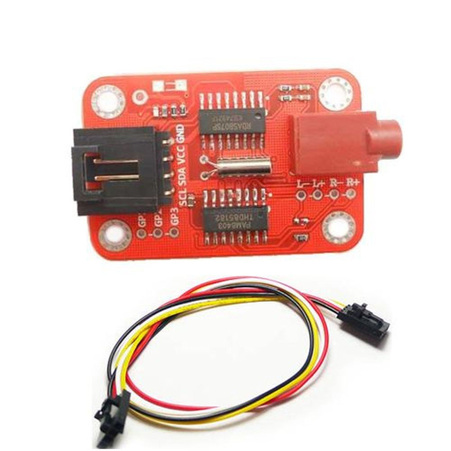 1 – Serial FM radio module with Amplifier
This module communicates with the Arduino through I2C interface. All commands are sent through I2C interface.
Features:
- On board 3W amplifier
- Standard 5V power supply
- I2C interface 5V TTL
- 3.5mm headset jack
This device is available from Ghost Box Hacks.
Download the FM Radio Arduino Library and Demo Software
Connect the Arduino to the FM Radio!
 Connect the Arduino to the FM Radio
Now we start the fun stuff!
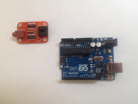
Look closely at your Arduino and Radio locate the following pins on both items:
On the radio– just to the inside of the board, behind the black connector.
You’ll need find the following: SCL SDA VCC GND
On the Arduino– locate the pins located on the two black connection bars.
You’ll need find the following: A5 A4 GND 5V
The two devices wire:
| Radio | Uno |
|---|---|
| GND | GND |
| VCC | 5v |
| SDA | A4 |
| SLC | A5 |
| GND | GND |
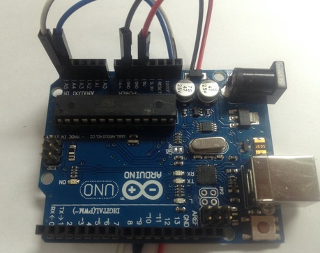
 Here’s how I connected mine for this demonstration.
I used some male to female single pin jumper wires.
This allows me to quickly change the setup if I decide to try something different in the future.
[divider]
Note the wires correspond to the chart below:
| Board | Uno | Wire |
|---|---|---|
| GND | GND | Black |
| VCC | 5V | Red |
| SDA | A4 | Blue |
[divider]
 The Radio Board has a couple items you can add.
The Output jack disables the amplifier when head phones are
plugged in.
If you want to use an external antenna and speakers, look close at the board and the picture I have to the left.
The Radio has an internal 3 watt amplifier. It’s plenty of load- we just need to add speakers … but you can just use headphones if you like.
The Radio uses the cord of your plugged-in head phone as the antenna, but they also gave us an external antenna connection as well.
Note where I added a single pin in the lower right hand corner.
** The PDF included in the Radio MFG zip file show this in detail. Download the FM Radio Arduino Library and Demo Software
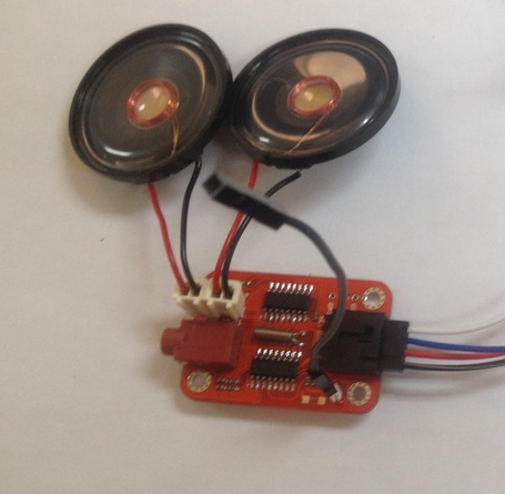
Here’s the way I use my radio board:
I added two speakers Right and Left since the radio is an FM stereo.
I also attached a wire for an external antenna.
That’s the basics.
We’ll add some more hardware next month:
A couple of switches and a battery in case you want to have a completely stand alone device.
Once the four wires are connected between the Uno board and the radio, you can use a set of head phones and run the “Box” using your computer.