I think the best thing we can do is blaze a trail, right or wrong forge ahead.
The paranormal field is so vast, so uncharted, that we all need to be inventors and pioneers!
If you’re a skeptic, that’s awesome… If you’re one of those “You’re wrong because I just know” or “I’ve never tried that but I know it doesn’t work”- then I feel sorry for you.
The idea is have fun! Try something new surprise yourself and let everyone else worry about what they’re doing!
First Step Toward Coding a Ghost Box
Let’s try some new code and take the first step towards a new ghost box!
This code will create a sweeping radio either up or down. 3 = up 4 = down
//  Based on the Origanl  sample code of  www.elechouse.com   @brief   example of FMRX_MODULE
//  This radio can be pruchased at  www.elechouse.com
//  GBH  1/2/2014 Mod for "Ghost Box "

#include
#include

float channel;
void setup(void)
{

  Serial.begin(9600); // setup serial communications to the host
  i2c_init(); // Setup IC2 for use pins (A4 and A5) arduino uno
  fmrx_read_reg(fmrx_reg_r); // Start FMRX
  fmrx_set_volume(8);// Set Default start up Volume
Changing the value on the next line will increase or decrease the signal strength used to determine the radio has found a station.
  fmrx_set_rssi(0); // This tells the radio what is a strong enough signal to stop on .. we use 0 -5 for better low signal responce
  fmrx_select_band(BAND_US);   //  select a band, parameter:  BAND_EU:       87-108MHz, Europe  BAND_US:       87-108MHz, USA  BAND_JP:       76-91MHz, JAPAN  BAND_JP_WIDE:  76-108MHz, JAPAN wide
  channel=fmrx_seek(SEEK_DOWN); // find a chanel to start on.
}
/* commands are 1 increase volume 2 decrease volume 3 scan  up x to exit 4. scan down x to exit */
void loop(void)
{
  static int vol=8;
  if(Serial.available()>0){
    switch(Serial.read()){
      case '1': // Increase Volume
        if(vol < 0x0F){
          vol++;
        }
        fmrx_set_volume(vol);
        Serial.print("Volume+:");
        Serial.println(vol);
        Serial.print("\r\n");
        break;

      case '2': // decrease volume
        if(vol > 0){
          vol--;
        }
        fmrx_set_volume(vol);
        Serial.print("Volume-:");
        Serial.println(vol);
        Serial.print("\r\n");
        break;

        case '3': // Scan up Exit on 'x'
        do{
        channel = fmrx_seek(SEEK_UP);
        Serial.print(channel);
        Serial.print("\r\n");
        delay(150); // change this amount to increase time stopped on a station
        if(Serial.read()=='x'){break;} // Enter  'x' to exit scan up
         }
        while (1==1);
        break;

       case '4': // Scan Down Exit on 'x'
       do{
        channel = fmrx_seek(SEEK_DOWN);
        Serial.print(channel);
        Serial.print("\r\n");
        delay(150); // change this amount to increase time stopped on a station
        if(Serial.read()=='x'){break;} // Enter  'x' to exit scan up
        }
        while (1==1);
        break;
    }
  }
}
If you didn’t get the radio software frmx.zip, download it now.
The FMX directory needs to be copied into your Arduino library directory. For information on how to add files into your library, read this guide.
Let’s go!
There’s always a learning curve the first time you start something like this.
The Arduino has a huge support community with thousnads of how-tos and help files to get you started.
If you get frusterated: I’m happy because that means you’re trying!
Programming
I won’t be posting any exotic code or cryptic commands. I’m going to try and make this simple, so first time programmers can see and understand.
Here’s the sample code from the manufacture on the radio board:
The Author of the program has added comments to help aid in understanding the program. The comments are displayed in red here.
========================================================================================================
/**
  @file    fmrx_demo.ino
  @author  www.elechouse.com
  @brief   example of FMRX_MODULE

    For this demo, input character '1' from serial monitor to seek channel down, '2' to seek down
 '3' to volume up, '4' to volume down.'&xxxx' (x is for a number) to manually set receive FM frequency

  @section  HISTORY

  V1.0 initial version

    Copyright (c) 2012 www.elechouse.com  All right reserved.
*/
/** include library */

#include <FMRX.h>
float channel;
void setup(void)
{
  Serial.begin(9600);
  Serial.print("FM-RX Demo By Elechosue\r\n");

  /** I2C initial */
  i2c_init();

  fmrx_power();
  fmrx_read_reg(fmrx_reg_r);
  Serial.print("FMRX Module Power up.\r\n");

  /** set volume */
  fmrx_set_volume(10);
  Serial.println("Volume Set");

  /** receive signal strength set, range:0-127*/
  fmrx_set_rssi(15);

  /**
    select a band, parameter:
    BAND_EU:       87-108MHz, Europe
    BAND_US:       87-108MHz, USA
    BAND_JP:       76-91MHz, JAPAN
    BAND_JP_WIDE:  76-108MHz, JAPAN wide
  */
  fmrx_select_band(BAND_EU);

  channel=fmrx_seek(SEEK_DOWN);
  Serial.println("Initial seek.");
  Serial.print("Channel:");
  Serial.print(channel, 2);
  Serial.println("MHz");
}

void loop(void)
{
  static u8 vol=10;
  if(Serial.available()>0){
    switch(Serial.read()){
      case '1':
        Serial.println("Wait...");
        channel = fmrx_seek(SEEK_DOWN);
        Serial.println("Seek down.");
        Serial.print("Channel:");
        Serial.print(channel, 2);
        Serial.println("MHz");
        break;
      case '2':
        Serial.println("Wait...");
        channel = fmrx_seek(SEEK_UP);
        Serial.println("Seek up.");
        Serial.print("Channel:");
        Serial.print(channel, 2);
        Serial.println("MHz");
        break;
      case '3':
        Serial.println("Wait...");
        if(vol < 0x0F){
          vol++;
        }
        fmrx_set_volume(vol);
        Serial.print("Volume+:");
        Serial.println(vol);
        break;
      case '4':
        Serial.println("Wait...");
        if(vol > 0){
          vol--;
        }
        fmrx_set_volume(vol);
        Serial.print("Volume-:");
        Serial.println(vol);
        break;
   /** check data for setting new channel. Input data must start with '&' and followed by 4 numbers, the first 3 is the integer part
    (Unit: MHz), the last one is the decimal part.And the channel must between 76MHz and 108Mhz.(eg: &0756 for 75.6MHz, and &0666 is out of range)
  */
        case '&':
        u8 i,buf[4];
         float ch;
         i=0;
         delay(30);
         while(Serial.available()&&i<4){
           buf[i]=Serial.read();
           if (buf[i]<= '9' && buf[i]>= '0') {
           i++;}
           else{
           i=0;
           break;
           }
         }
         if (i==4){
           ch = (buf[0]-'0')*100+(buf[1]-'0')*10+(buf[2]-'0')*1+0.1*(buf[3]-'0');
           Serial.println(fmrx_set_freq(ch),2);
         }else{
           Serial.println("Input Error.");
         }
         /** dummy read for useless character */
         while(Serial.available()){
           Serial.read();
         }
         break;
    }
  }
}
=====================================================================================================================
Ok! Take a breath! It’s not that bad- it just looks crazy.
My goal is to make you comfortable with building, running and modifying your very own ghost box. Then you can decide just how it should work and why!
So let’s tear into it a few lines at a time.
The Code Title
The first couple of lines of real code are the Code Title area.
Here is where the author is telling you who wrote this app and where they can be find. They also tell you the way the intend the code to work and any other info.
Remember: comments are in red. They are not acutal code, just author notes.
/**
  @file    fmrx_demo.ino
  @author  www.elechouse.com
  @brief   example of FMRX_MODULE

    For this demo, input character '1' from serial monitor to seek channel down, '2' to seek down
 '3' to volume up, '4' to volume down.'&xxxx' (x is for a number) to manually set receive FM frequency

  @section  HISTORY

  V1.0 initial version

    Copyright (c) 2012 www.elechouse.com  All right reserved.
*/
Alright, so that’s telling us that elechouse.com made the fmrx demo and how it works.
Including Libraries
Next we really start to build the program. Here is where the author sets up what library the Arduino will be using. A library is a simple set of additional code that’s grouped together. Libraries make it easier to create complex programs.
/** include library */
#include
Not too bad. There’s only one library called for in this basic program.
Declaring Functions
Now let’s look at the first section of the main program. Here the Author starts out by declaring a function called setup:
Communication is setup communicate to the computer and the Arduino:
Serial.begin(9600);
Command is issued to signal to the computer the program is active:
Serial.print("FM-RX Demo By Elechosue\r\n");
Radio module communication is started:
  /** I2C initial */
  i2c_init();
Radio is not turned on “Initialized”:
fmrx_power();
fmrx_read_reg(fmrx_reg_r);
Announce the Radio is running:
Serial.print("FMRX Module Power up.\r\n");
Set up the operations for the radio (volume, signal strength and band):
 /** set volume */
  fmrx_set_volume(10);
  Serial.println("Volume Set");

  /** receive signal strength set, range:0-127*/
  fmrx_set_rssi(15);

  /**
    select a band, parameter:
    BAND_EU:       87-108MHz, Europe
    BAND_US:       87-108MHz, USA
    BAND_JP:       76-91MHz, JAPAN
    BAND_JP_WIDE:  76-108MHz, JAPAN wide
  */
  fmrx_select_band(BAND_EU);

  channel=fmrx_seek(SEEK_DOWN);
  Serial.println("Initial seek.");
  Serial.print("Channel:");
  Serial.print(channel, 2);
  Serial.println("MHz");
}
Ok, now we have the radio, Arduino and the computer all attached and talking.
Setup and ready to Rock
Next … time to do something.
void loop(void)
{
Next it set up a couple variables that this program will need:
      case '4':
        Serial.println("Wait...");
        if(vol > 0){
          vol--;
        }
        fmrx_set_volume(vol);
        Serial.print("Volume-:");
        Serial.println(vol);
        break;
  /** check data for setting new channel. Input data must start with '&' and followed by 4 numbers, the first 3 is the integer part
    (Unit: MHz), the last one is the decimal part.And the channel must between 76MHz and 108Mhz.(eg: &0756 for 75.6MHz, and &0666 is out of range)
  */
If the input is a &, execute this code:
        case '&':
        u8 i,buf[4];
         float ch;
         i=0;
         delay(30);
         while(Serial.available()&&i<4){
           buf[i]=Serial.read();
           if (buf[i]<= '9' && buf[i]>= '0') {
           i++;}
           else{
           i=0;
           break;
           }
         }
         if (i==4){
           ch = (buf[0]-'0')*100+(buf[1]-'0')*10+(buf[2]-'0')*1+0.1*(buf[3]-'0');
           Serial.println(fmrx_set_freq(ch),2);
         }else{
           Serial.println("Input Error.");
         }
         /** dummy read for useless character */
         while(Serial.available()){
           Serial.read();
         }
         break;
    }
  }
}
What FMRX program does.
Seems like a lot, but it’s really a pretty simple program.
Here’s what frmx is doing:
Grab a library to tell us about the radio.
Setup the basic items we need.
Look for inputs from the host computer.
Execute the input code.
Repeat at # 3.
Run FMRX_demo on your Arduino now!
Download the Manufactures example code, install the Arduino program on your computer, Mac, PC or Linux.
Compile the FMRX_demo program and upload it to your Arduino!
Miss something? You bet. For more help with setting up your Arduino Search the web there are thousands of sites that help the first time user.
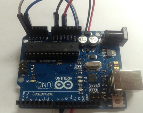
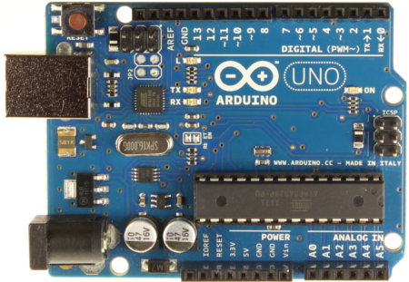
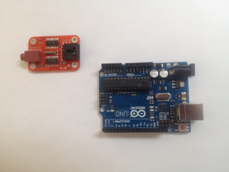
1 – Arduino and USB cable
For this Project we will be using the Arduino Uno R3.
This is a processor board with built in interface for USB. Easily available from numerous sources including our own Ghost Box Hacks.
The Arduino Uno is a microcontroller board based on the ATmega328 (datasheet). It has 14 digital input/output pins (of which 6 can be used as PWM outputs), 6 analog inputs, a 16 MHz ceramic resonator, a USB connection, a power jack, an ICSP header and a reset button. It contains everything needed to support the microcontroller; simply connect it to a computer with a USB cable or power it with a AC-to-DC adapter or battery to get started.
There are several types of Arduino boards, however we will only be using the UNO. Most all the Adruino versions will work for these projects, but it may be easier for beginners to follow the Arduino Uno R3.
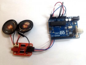
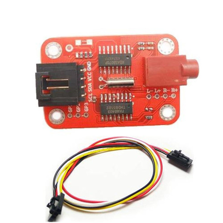
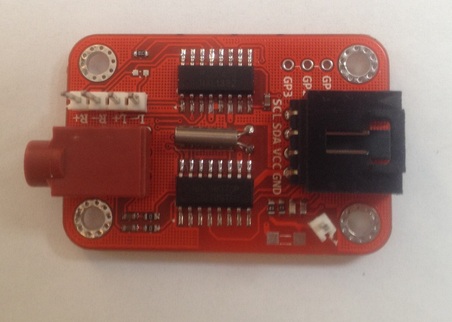
1 – Serial FM radio module with Amplifier
This module communicates with the Arduino through I2C interface. All commands are sent through I2C interface.
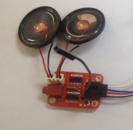
Here’s the way I use my radio board:
I added two speakers Right and Left since the radio is an FM stereo.
I also attached a wire for an external antenna.
That’s the basics.
We’ll add some more hardware next month:
A couple of switches and a battery in case you want to have a completely stand alone device.
Once the four wires are connected between the Uno board and the radio, you can use a set of head phones and run the “Box” using your computer.
 I think the best thing we can do is blaze a trail, right or wrong forge ahead.